Category

Theme images by Storman. Powered by Blogger.
Best viewed in Google Chrome

Labels

Labels

Advertisement

Popular Posts

Services

Showing posts with label Direct Reduction. Show all posts

Direct Reduction (DR) Processes - First No Coke Option for Iron Making

- No comments
19-Dec-2009

The first no coke method of iron making units is Direct Reduction (DR Process). Direct reduction processes can be divided into those using non-coking coal (as in rotary kiln and rotary hearth furnace based processes) and those using natural gas (as in shaft furnace, fluidized bed furnace, and fixed bed furnace based processes). DR processes using coal have been found to be more suitable in areas, which have local sources of coal and ore but no natural gas. On the other hand in gas-rich areas, gas-based DR (larger in size and more energy efficient) is the automatic choice.

A large number of DR (direct reduction) processes are available today, which can be grouped as follows:
  • Coal based direct reduction (DR processes) using rotary kilns such as SL/RN, DRC, TDR, Jindal, Codir, Accar, SIIL and OSIL. 
  • Coal based direct reduction (DR processes) using rotary hearth furnaces such as Fastmet, Inmetco, Circofer and Sidcomet etc. 
  • Batch type gas based processes using retorts - HyL I. 
  • Continuous processes in a shaft furnace using reformed natural gas as the reductant such as Midrex and HyL III. 
  • Gas based processes using a fluidized bed - Fior, Finmet, Circored.  
  • Special processes for treating waste oxides such as Primus using a multi-hearth furnace.
We have described most of these DR (Direct Reduction) processes separately and individually in this Blog since, it will be too lengthy to put all of them at one place. To know more about each of the DR processes simply type the name of the process in the search box placed near the top of this Blog and search. Alternatively you may select and click on the name of the process from the list of KEYWORDS given in the sidebar.                 

HYL III and SL/RN - The two widely accepted Direct Reduction (DR) Processes of ironmaking

- No comments

10-Oct-2009

Direct Reduced Iron (DRI) is obtained by reducing lumps as well as fines of iron ore in solid state at a relatively low temperature of around 1000OC. A large number of DR processes are available today. SL/RN and HYL are two such DR processes. While HYL is a batch-type gas based process and uses a countercurrent shaft-furnace, the SL/RN process utilizes rotary kiln to reduce lump ore, pellets and sand iron with coal. Here we will discuss about some key features, including advantages and disadvantages of these two DR processes.

HYL III
https://www.industry.guru
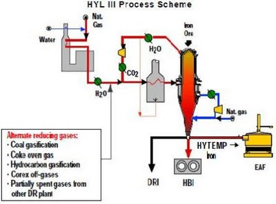
Fig: HYL III Process Scheme


The HYL process was developed in Mexico and was the forerunner of the HYL III direct reduction technology. In HYL I process, a mixture of gases containing about 89% of reducing compounds is used. Each reduction module in HYL plant consists of four units - three “in line” and the fourth in “turn around” mode. The principal change made over HYL I in HYL III was the modification of the four fixed bed reactors by a single moving bed reactor, utilizing the same gas reforming plant, auxiliary equipment and quenching towers.  Actually HYL III technology is characterized by its wide flexibility for adapting to special needs, depending on available reducing gases, energy use and melt-shop requirements. Use of spent gases from direct ironmaking processes, coal gasification, energy optimization in DR plants and technology developments aimed to improve EAF productivity have been the objective of HYL. Some distinctive features of HYL III process are:

Fig: HYL III - COREX Off-Gas Process Scheme
=> The H2/CO of the reformed gas is 3, the temperature is about 930OC, the inside pressure of the countercurrent shaft-furnace is 450 kilopascals and the energy required for the reduction is basically the same as in the MIDREX process.
=> The selective elimination of H2O and CO2 from the reducing gas circuit allows maximum recycle of the reducing gases to the reduction reactor. Hence, the reducing gas make-up and the process natural gas consumption are minimized.
=> The reducing gas generation and the reduction sections of a HYL III unit are independent from an operational point of view. This feature offers important flexibility for adapting to different reducing gas sources. The process schemes based on use of alternative reducing gases from different sources and other DR/ Ironmaking sources have been proven in HYL III plants. Such alternate sources of reducing gas can be -
  • Coal gasification processes.
  • Coke oven gas.
  • Gases from Hydrocarbon gasification.
  • Partially spent gases from another DR plant.
  • COREX off-gases.
=> High pressure operation (4 atmospheres or more) enables the effective control of process conditions, with smaller equipment size for gas handling and lower energy requirements (9.0 - 10.0 GJ/t).
=> The process is much flexible as far as raw material use is concerned - while it operates best with 100% pellets, even 100% lump ore of a suitable type has been used, but it is suggested to use a mixture of pellets and lump ores.   
=> This technology offers the unique flexibility to produce three different product forms depending on the specific requirements of each user - Cold DRI, HBI and HYTEMP iron. Metallization can be controlled up to 95% and Carbon content 5.0%.
=> When combined with COREX off-gas as a source of reducing gas, the HYL III DR plant offers high productivity using available spent gas and benefits in steel production using HYTEMP® iron together with hot metal in EOF/BOF based steel mills.
=> The HYL III process features the flexibility of generating electric power, taking advantage of high pressure steam produced in the natural gas-steam reforming unit which can be used in a turbo generator or in a set of turbines, at a high generation capacity.
According a data of recent past, around 11 million tones of direct reduced iron (DRI) was produced in 2003 by this process in India, Grasim’s HYL plant at Raigad (Orissa) produced 0.75 million tones of HBI.     

SL/RN
SL/RN is the most widely accepted coal based DR process. It was jointly developed by Stelco, Lurgi Chemie, Republic Steel Company and National Lead Corporation in 1964. In this process, the materials charged into the kiln gravitate towards the discharge end during which they are progressively heated to the temperature of reduction of around 1000 - 1100OC. The product discharged from the kiln is cooled in an extremely cooled rotary cooler around 100OC before being subjected to magnetic separation to separate sponge iron from coal ash and char. Waste gases leaving the kiln at the inlet end pass through a dust chamber and a post combustion chamber, before being cooled and cleaned in electrostatic precipitators, scrubbers or bag filters. In SL/RN technology the clean gases can be used in waste heat boilers to recover the sensible heat and the steam generated can be utilized for heating purpose or for electric power generation. Some distinctive features of SL/RN process include:
=> Flexibility with regard to the type of iron bearing materials which can be used such as lump ore, pellets, ilmanite, iron sands and steel plant wastes.
=> Use of a wide variety of solid fuels ranging from anthracite to lignite and charcoal.
=> Improved heating of the charge by submerged air injection in pre-heating zone of the kiln. This process suffers, however, from relatively big heat loss and facility size.
=> SL/RN technology provides optimized coal injection facilities at the discharge end of the kiln.
=> Waste gas conditioning by controlled post combustion followed by power generation (the power generated is more than the requirement of the plant).
The original SL/RN process has been modified in a variety of ways, particularly in India where rotary kiln DR technology has been widely applied.            

MIDREX - The Most Widely accepted Direct Reduction (DR) Process of Ironmaking

- No comments
2-Oct-2009

Midrex the most widely accepted direct reduction (DR) process of ironmaking in the world was developed by Midland Ross Corporation of Cleveland, USA in 1967 , has the following distinctive features:
Recommended Natural Gas Composition for MIDREX Plants
Components
Vol %
Effects
CH4
C2H6
C3H8
C4H10
+C4 (Hydrocarbon)
CO2
N2
S
75 - 100
0 - 25
0 - 4
0 - 2
0 - 0.5
20 max
20 max
20 ppm.
(max Wt.)
--
--
Above 4% C3H8, water vapour content should be increased.
--

Above 20% CO2, export fuel is produced.
For every 10% of N2, fuel consumption increases by 2%.
Above 20 ppm, carbon deposition on catalyst.

MIDREX Process - Some Features
=> It allows the production of highly metalized DRI (exceeding 92%, see adjacent Table showing typical composition of Midrex DRI) and the carbon content of can be controlled in the range of about 1.0 - 2.0%.
=> Although originally developed for use with high grade pellets, the Midrex shaft furnace is now able to use some amount of lump ores. Optimum process conditions are often obtained by mixing 30-50% of an appropriate type of lump ore with high grade pellets. See adjacent Table showing Physical Characteristics of Pellets and Lump Ores used in the MIDREX Process.  
=> Fuel utilization in Midrex process has steadily decreased from an average of 12.5 - 14 GJ/t of DRI to 9.5 - 10.5 GJ/t. This improvement in energy efficiency has been the result of higher reduction temperatures, enrichment of reduction gas with methane, utilization of in-situ reforming, and pre-heating of the process gas utilizing waste heat from the reformer.
=> Following the advent of in-situ reforming, oxygen carriers from an external source are now not required in the production of reformed gas. Therefore, the investment cost and operating costs of Midrex units have been reduced.
=> The DRI produced is relatively active towards re-oxidation, particularly when moisture is present. Hence it must be deactivated if it is to be stored or transported over a long distance.    
Physical Characteristics of Oxide Feeds
(Pellets and Lump Ores) used in the MIDREX Plants

Pellets
Lump Ores
Screen analysis (wt %)
50 - 31.75 mm
31.75 - 6.3 mm
+ 15 mm
8 - 15 mm
– 8 mm
– 6.3 mm
Bulk Density (t/m3)
Compressive Strength (kg/pellet)
ISO Tumbler Test (wt%)
+ 6.3 mm
– 0.5 mm

--
--
10% max
85% max
5% max
--
2.0 - 2.1
270 min


95% min
4% max

5% max.
93% max.
--
--
--
7% max
2.0 - 2.6
--


--
--

Typical Product Composition of Midrex DRI
Content
Wt %
Fe (total)
Fe (metallic)
Metallization
SiO2
Al2O3
CaO
MgO
S
P
92 -93
84 - 88
93 - 95
2.0 - 3.5
0.5 - 1.5
0.2 - 1.6
0.3 - 1.1
0.005 - 0.015
0.02 - 0.04
Related Articles 

What is FASTMET Process of Ironmaking ?

- No comments
11-Sept-2009
Fastmet The Process Concept and References  
This is a direct reduction process using a Rotary Hearth Furnace (RHF) which was derived from the work done in USA by Midland Ross and Surface Combustion, in the ‘Heat Fast’ process, treated in 1960s. It is a solid reductant based process in which iron ore concentrate, pulverized coal and a binder are mixed together and pelletized. The resulting green pellets are fed either to a drier or directly to a rotary hearth furnace where the pellets are heated to 1250 - 1400OC and reduced to metallic iron. Burners and post-combustion the CO evolved provide the heat required to raise the pellets to the reduction temperature.
The first commercial Fastmet plant was commissioned at the Hirohata Works No.1 of Nippon Steel in April, 2000 and Hirohata Works No.2 in February, 2005 with material processing capacities of 190000 tpa each plant. The second plant established was Kobe’s Steel’s Kakogawa Works started from April, 2001 having a material processing capacity of 16000 tpa.  The Fastmet process has allowed the Kakogawa Works to achieve a zero emission rating of steel mill waste. Waste utilization is the principal application of the Fastmet process in Japan.       
FASTMET Process - Flowchart
Advantages of Fastmet


Some of the advantages of Fastmet process as have been reported are summarized as follows:
=> A wide variety of iron ore as well as steel mill wastes including BF dust, BF Sludge, BOF dust, Sinter dust, EAF dust, mill scale, and etc. can be used as the oxide feed.
=> Elimination of waste disposal cost and landfill liability as wastes is changed to a quality source of iron (DRI).
=> Recovery of Zinc contained in wastes (Zn deriving from scrap) which can be sold to zinc producer. Zinc removal: 95% or higher.
=> A wide variety of energy sources can be utilized including natural gas, LPG, coke oven gas, heavy oil, coke breeze and carbon bearing wastes or pulverized non-coking coal.
=> The short reduction time of less than 12 minutes enables easy plant starting and shut-down, and quick adjustment of production rate.
=> Reclamation of carbon is possible. Carbon contained in dusts will be used as reductant. The carbon content of DRI can be adjusted as per the customer’s requirement.
 Related Articles –