Category

Theme images by Storman. Powered by Blogger.
Best viewed in Google Chrome

Labels

Labels

Advertisement

Popular Posts

Services

Showing posts with label Phase Diagrams. Show all posts

Dissolution Kinetics of MgO-CaO and MgO-Cr2O3 (Mag-Chrome) Refractories in Secondary Steel Slag and the Binary Phase Diagrams

- No comments

MgO-CaO Phase Diagram
Refractory Lining: MgO-CaO Binary Phase Diagram image
Fig: MgO-CaO binary Phase Diagram

The above figure shows the phase diagram of MgO-CaO binary system. The solid solubility at high temperatures leads to formation of a high temperature bond in dolomite refractories.   
MgO-Cr2O3 System (MgO-MgCr2O4 Phase Diagram)
Refractory Lining | Steel Technology: MgO-MgCr2O3(Magchrome spinel)
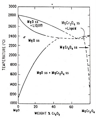
Fig: MgO-MgCr2O4 binary Phase Diagram

The only intermediate compound which exists in the binary system MgO-Cr2O3 is Magchrome spinel (MgO.Cr2O3 or MgCr2O4). From the above phase diagram of Magnesite-Magchrome spinel (MgO-MgCr2O4) binary system it can observed that for steel plant refractories direct bonding between magnesia-chrome phase is formed when these two are heated together at temperatures above 1600OC as a result of the partial solubility of the constituents.      
Dissolution Kinetics of Refractory Oxides
Refractories are non-metallic materials used for the lining of kilns and furnaces required for high temperature operations in several metallurgical and non-metallurgical industries such as iron & steel, aluminium, copper, glass, cement, petrochemicals etc.
Dissolution of solid oxides in liquid slag is governed mainly by –
(1) Chemical reaction at the slag / refractory interface,
(2) Transport or diffusion of reacting species.
In the second case, rate of dissolution can be expressed in terms of Nernst equation:
J = D (Cs – Cm) / ∂
Where, D is the diffusion coefficient (m2 s–1), Cm and Cs are, respectively, concentration and saturation solubility of refractory in slag (g m–3), and ∂ is the effective boundary layer thickness (m). Increasing D or decreasing ∂ (i.e. increasing D/∂) result in increase of dissolution rate, J. Moreover, it is also clear from the above equation that the value of (Cs – Cm) strongly influences the dissolution rate. If slag is saturated with refractory oxide then J = 0. Naturally, to minimize rate of dissolution, it is necessary to minimize (Cs – Cm). For example, with increasing MgO content in the slag, the corrosion of the periclase phase in Mag-Chrome refractories will decrease. If Cm = 0, then the value of (Cs – Cm) reaches a maximum and thus, so does the dissolution rate.
Dissolution kinetics of MgO-CaO and Magnesite-chrome refractories in secondary steel slag was studied by Chen Zhaoyou Wu Xuezhen Ye Fangbao at Luoyang Institute of Refractories Research by means of the rotating cylinder method [See details]. Materials investigated include four MgO-CaO samples (MgO content: 40 to 93%) and two magnesite-chrome samples (co-clinkered and semi-rebonded). The experiments were carried out in Argon atmosphere at different temperatures (1600-1750OC) and revolution speeds (200 to 500 rpm) using synthetic slags similar to VOD and AOD slags with different basicities (0.6-2.68). Based on their experimental results the mechanism and kinetics of the dissolution process are discussed. The conclusions drawn are as follows:
1. Erosion resistance of magnesite-chrome (MgO-Cr2O3) refractories is better than that of MgO-CaO materials.
2. When the content of MgO is about 60-80%, slag dissolution resistance of MgO-CaO samples will be comparatively higher. When basicity of slag is 1.0, the dissolution rate of magnesite-chrome refractories (i.e. Mag-Chrome, MgO-Cr2O3) is much lower than that of MgO-CaO.
3. With increase of basicity of slag, the dissolution rate of magnesite-chrome increases, whereas that of MgO-CaO decreases.
4. For the increase of temperature of 100OC at one time, the dissolution rate of MgO-CaO increases by 2-3 times while that of magnesite-chrome increases 5-6 times. Dissolution activation energy for MgO-CaO refractory is 70 kcal/mol and that for magnesite-chrome is 110 kcal/mol. The diffusion coefficient of MgO in the slag is 3.7×10~(-5)cm~2/s.
5. M_2S is formed by magnesite-chrome with acid slag in the reaction zone while C_2S is formed by MgO-CaO with basic slag in the reaction zone.
6. The process of dissolution of MgO-CaO refractories in slag is controlled by the diffusion mechanism.      

Refractory Formation in Alumina - Chrome - Silica (Al2O3 - Cr2O3 - SiO2) System along with the Ternary Phase Diagram

- No comments

9-Dec-2009

Alumina - Chrome - Silica (Al2O3 - Cr23 - SiO) Refractory System

Most of the work and so, data are limited to the binary systems forming the edges of the Alumina - Chrome - Silica ternary system. Very few data are available on the phase relations in this ternary refractory oxide system. At first a partial liquidus diagram for this system was published by Born [V.A. Born, Transactions. 5th Conference Exper. Techn. Min. Petr. Publ. Acad. Science, USSR, 1958, p.479]. Solacolu [S. Solacolu in “Proceedings of the 8th conference on the Silicate Industry, (SiliConf.)”, Hungary, 1965, p.777] proposed an equilibrium diagram (see adjacent Fig.) for the Alumina - Chrome - Silica (Al2O3 - Cr23 - SiO) ternary refractory oxides system in which he divided it into two subdivisions:
(I) Subsystem SiO2 - 3Al2O3.2SiO2 - Cr2O3 contains three binary eutectic points e1, e2, and g3; and one ternary eutectic point E1, melting at 1580OC,
(II) Pseudo-subsystem Al2O3 - 3Al2O3.2SiO2 - Cr2O3which contains no ternary eutectic point. 
 Fig. - Thermal Phase Equilibria in the Alumina - Chrome - Silica (Al2O3 - Cr23 - SiO) system (After Solacolu)
Fig. - Phase equilibrium diagram for the system Alumina - Chrome - Silica (Al2O3 - Cr23 - SiO). Heavy lines are boundary curve, dashed lines are liquidus isotherms in degree Centigrade, and the two-liquid region is outlined by the zone of dots. (After Roeder et al.) 
From his observations Solacolu concluded that the body composition should be chosen from subsystem (II), especially in hatched quadrangle, where melting temperatures are above 2000OC. It may be mentioned here that the phase diagrams for different bounding binary systems as were adopted by Solacolu, are those given by Bowen and Grieg [N.L. Bowen and J.W. Grieg, Journal of American Ceramic Society, 7(4), 1924, p.238], Schairer [J.F. Schairer, Journal of American Ceramic Society, 25, 1942, p.241] and Bunting [E.N. Bunting, J. Res. Natl. Bur. Std. 5(2), 1930, p.325].
Bunting’s binary phase diagrams were also accepted by Roeder, Glasser, and Osborn [R.L. Roeder, F.P. Glasser and E.F. Osborn, Journal of American Ceramic Society, 51(10), 1968, p.585], who later on published a phase diagram for Alumina - Chrome - Silica system (see adjacent Fig.). For Al2O3 - SiO2 (alumina - silica system) Roeder et al. adopted the diagram of Aramaki and Roy. The major differences between these two phase diagrams of Alumina - Chrome - Silica system are that Solacolu omitted the two liquid region and he assumed that ternary liquids are in equilibrium with pure chromium (Cr2O3) crystals rather than with corundum solid solutions  (Alumina - Chrome solid solution). Roeder et al. concluded that at 1580OC (ternary eutectic), the eutectic liquid (6Al2O3 - 1Cr2O3 - 93SiO2) coexists with a mullite solid solution (19Al2O3 - 81Cr2O3), and crystoballite (SiO2). They presented also the diagrams to show courses of fractional crystallization, courses of equilibrium crystallization, and phase relations on isothermal planes at 1800O, 1700O, and 1575OC.
Murthy and Hummel [M. Krishnamurthy and F.A. Hummel, Journal of American Ceramic Society, 43(5), 1960, p.267] presented data suggesting maximum solubility of Cr2O3 in mullite of 8 to 10% at 1600OC, while the beneficial influence of chromium on the resistance of alumino - silicate refractories like, mullite, sillimanite to the action of ferruginous slags also estimating the maximum solubility of chromium (Cr2O3) in these refractories under equilibrium conditions at 1600OC, were pointed out by Chadeyron et al. [A.A. Chadeyron and W.J. Rees, Transactions of British Ceramic Society, 42, 1942, p.163] and Ford and Rees. Under equilibrium conditions at 1600OC, mullite can take into solid solution up to 8% by weight of chromium. Further addition of chromium results in dissociation of mullite, most of the alumina (Al2O3) forming a solid solution with chromium (Cr2O3), while the remainder of the alumina (Al2O3) melts with the silica precipitated as a result of the dissociation. They also showed that a marked increase in the resistance of sillimanite to ferruginous slag was effected by incorporation of up to 15% of chromium.
Herabi and Davis studied the effect of varying amount of chromium (Cr2O3) and addition of mullite on densification of modified corundum ((Alumina - Chrome solid solution) [A. Herabi and T. Davis, Journal of Euro Ceramics, 2, 1989, p.2576]. On the basis of their studies these authors concluded that mullite modified corundum refractories show better Microstructural states and mechanical strength.
Sintering behaviour in the Alumina - Chrome - Silica (Al2O3 - Cr23 - SiO) Refractory System (Mullite - Chrome) in the reducing atmosphere was investigated by Yamaguchi [A. Yamaguchi, Ceramic International, 12(1), 1986, p.19]. In Yamaguchi’s experiment mullite was not formed from alumina and silica in the presence of chromium (Cr2O3) at high temperatures from 1300OC to 1500OC, and it was even thought to decompose to alumina (Al2O3), gaseous SiO, CO2 and CO.

Despite these contradictory reports, the author of this article (Dr. Abhijit Joardar), and Yang and Chan [Proceedings of the International Symposium of on Refractories”, Nov. 15-18, 1988, Hangzhou, China] found mullite to grow at the expense of corundum and silica phases better in Chromium - containing high alumina refractories than Chromium - free refractories.

Mullite and Other Alumino-Silicate Refractories vis-à-vis Alumina - Silica (Al2O3 - SiO2) Binary Phase Diagram

- 3 comments

23-Nov-2009

Alumino-Silicate Refractories
Aluminosilicate or Alumino-Silicate minerals are the naturally occurring compounds mainly composed of aluminium, silicon and oxygen. These minerals are the major constituents of Kaolin and clay minerals. Besides Fireclay, Kyanite, Sillimanite, Andalusite and Mullite are some alumino-silicate minerals which constitute the main raw materials for Alumino-Silicate refractories. By themselves, these minerals especially sillimanite and Andalusite have a high melting point, low coefficient of expansion after heating and excellent resistance to alkaline melts. Kyanite, Sillimanite, Andalusite and all other sillimanite group of minerals break down at or below 1545OC and yield Mullite. Mullite is 3Al2O3.2SiO2 (71.8% Alumina, 28.2% Silica by weight), and is found naturally or is formed by firing combinations of alumino-silicate raw materials or aluminous raw materials. From the Alumina - Silica (Al2O3 - SiO2) phase diagram below, it is clear that a mullite material with more than 73 wt% Alumina (Al2O3) will consist of mullite and alumina. Below 70 wt% Alumina (Al2O3), the material will contain mullite and silica. In these two cases, the temperatures at which the liquid will first appear are radically different.
By varying the alumina and silica ratio in alumino-silicate refractories, a wide range of properties can be realized. Low-alumina, high-silica refractories are used in areas where high strength at service temperature is required such as steel ingot soaking pits. Alumino-Silicate refractories with 30 - 45% alumina (Fireclay refractories) have high-temperature volume stability and strength, excellent resistance to thermal spalling etc. because of which fireclay refractories are widely used in various metallurgical and non-metallurgical industries, furnace back-up lining and so on.    
Fig: Versions of the binary phase diagram of the Alumina - Silica (Al2O3 - SiO2) system proposed from time to time (a) Bowen and Grieg, Schairer (b) Aramaki and Roy (c) Aksay and Pask

A Review of Previous Work on Alumina - Silica (Al2O3 - SiO2) Phase Diagram in relation to the Formation of Mullite  
The Alumina - Silica (Al2O3 - SiO2) refractory oxides system has been the subject of several investigations in the past. Though many papers were presented on the melting relations and range of composition of mullite, it remained a matter of controversy about the diagram in the region of the compound mullite (3Al2O3 : 2SiO2) as has been discussed by Aramaki and Roy [Journal of American Ceramic Society, 45(5), 1962, p.229]. The first equilibrium diagram for the Alumina - Silica (Al2O3 - SiO2) system presented by Bowen and Grieg [Journal of American Ceramic Society, 7(4), 1924, p.238] as shown in the adjacent phase diagram fig (a), shows incongruent melting of mullite. Other significant features which could not be explained on the basis of this phase diagram, e.g. deviation from stoichiometry of the composition of mullite found in refractory bricks, and the crystallization of mullite from a melt of its compositional range, could now be understood with the modifications introduced in the phase diagram by Aksay and Pask [Journal of American Ceramic Society, 58(11 - 12), 1975, p.507] as shown in fig (c). According to this phase diagram showing the stable phases (solid line) and two meta-stable versions (dashed and dot-dashed lines) in the Alumina - Silica (Al2O3 - SiO2) system, mullite melts incongruently at the peritectic 1828OC on the International Practical Temperature Scale of 1968 (IPTS-68) to a liquid containing about 53 wt% Alumina, which is far from the compositional range of stable mullite solid solution (70.5 - 74.0 wt% Alumina). In the phase diagram of Aramaki and Roy as shown in fig (b), mullite is shown to melt congruently at 1850OC on the International Temperature Scale of 1948 (ITS-48), the second eutectic between mullite and corundum, 1840OC, is located at 77.5 wt% Alumina. The major changes introduced in the latest diagram (fig. c) are:
(i) The eutectic temperature was raised to 1595OC by Schairer in 1942; the eutectic composition was also shifted.
(ii) Mullite was found to have a narrow but stable range of solid solution among other by Aramaki and Roy, around the stoichiometric composition of mullite, 3Al2O3.2SiO2, determined by Bowen and Grieg.
Because of the excellent load bearing capacity, volume stability, high resistance to glass, molten metal and slags, mullite refractories find wide spread applications in the glass and metallurgical industries. They are also used as kiln furniture.