Category

Theme images by Storman. Powered by Blogger.
Best viewed in Google Chrome

Labels

Labels

Advertisement

Popular Posts

Services

Showing posts with label Refractory lining installation. Show all posts

How effective are Insulating Refractory (Ceramic) Fibers?

- No comments
24-April-2010

With the advancement of technology and involvement of very high temperatures by various industries as well as continuously increasing energy costs, there has been always a demand for new and more dependable insulating materials. Finally, there has been one of the most exciting developments in the field of high temperature insulation as ceramic fibers. These are a family of insulating refractory products based on refractory or ceramic fibers. Such products are very light and highly porous resulting in an excellent insulating efficiency with decrease in the material consumption of insulators by 40 to 60 percent. Thus use of such materials reduces overall weight of the structure, reduces fuel consumption and increases the productivity. These materials have seen rapid sales growth in recent years because of their excellent insulating properties, light weight, and ease of installation. Most refractory fiber materials are basically high temperature fiberglass materials. They have alumina-silica compositions made from pure alumina and silica or from kaolin clay. There are also chemically made alumina (Al2O3) fibers which are useful for high temperatures but which are quite expensive. Zirconia fibers (generally glass bonded zircon) have also found considerable market acceptance for service up to 3300OF or even a little higher. [Insulating refractories in general, their types, raw materials used for their manufacturing, method of heat - flow through such refractories and its calculations, what should be the thickness of insulating refractory linings etc. have been discussed in detail in posts Insulating Refractories (Part - I) and Insulating Refractories (Part - II)].   

Refractory fiber products can take on a variety of forms.
Bulk fiber can be used for packing or stuffing. The fiber can be collected into a mat and wetted with an organic binder. When this binder is cured it yields a felt. Available in flexible rolls in densities of 3, 4, 6, and 8 pcf (lb/ft3) or in sheets passed to densities as high as 24 pcf, these felts have served a wide variety of purposes. Another development has been the production of binder-free blankets. Often these have the fibers mechanically interlocked by a “needling” process which substantially increases mechanical strength without the using any organic binder. Mechanical strength at high operating temperatures is thus preserved, since any organic binder burns out during initial heat-up. Refractory fibers can also be vacuum formed to give rigid board and shapes, such as combustion chambers. A tremendous variety of products have thus resulted. Just to mention a high technology application, the insulating tiles on the re-entry surfaces of the Space Shuttle are of this type. Formulated of ceramic fibers and with a special ceramic bond, those tiles are capable of withstanding extremely high surface temperatures and temperature gradients without failure, while protecting the vehicle substructures by virtue of their very low thermal conductivity.

Typical Thermal Conductivities for Refractory Fiber Blanket Materials graphics
Refractory Fiber products have unique properties.
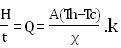
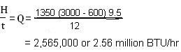
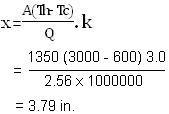
In many respects they have revolutionized insulating refractory lining technology. Refractory Fiber products have exceptionally low thermal conductivity values, as can be seen in the adjacent figure (graph) given for typical refractory fiber blanket products. Note that the higher density materials have lower k values. Most of the heat transfer occurring in fiber products is by radiation. Higher density fiber products have more fibers in the same volume and thus block radiation more effectively. Solid conduction is minimal, since an 8 pcf fiber blanket contains 95% air. Air conduction is also important, however. Note that the k values increase rapidly as the temperature increases. This too, is the result of the major role that radiation plays in energy transport in refractory fiber materials. The low density of refractory fiber means that very lightweight insulation systems are possible. Furnace or kiln linings can be exceptionally light. This also results in very low heat storage, which is very important in cyclical operation. It allows rapid heat-up and cool-down and is a major factor in energy conservation with these materials. Insulating refractory fiber linings also greatly reduces the mechanical load on supporting structures, so that these can be made lighter and less expensive. The resilience of fiber materials makes thermal shock practically impossible. Extraordinarily rapid temperature changes have no effect on refractory fibers or their mats. Various types of felts based on ceramic fibers and available in rolls have proved to be useful as their use promote speedy laying with minimum joints. They also guarantee a unique advantage of lining surfaces bearing complicated contours.   
TABLE: Thermal Comparison of Refractory Fiber Lining with IFB and Fireclay
Brick Linings for Furnace Operating at 1800OF
Wall Construction
Heat Loss (BTU/ft2/hr)
Heat Storage (BTU/ft2)
Cold Face (OF)
Lining Weight (lbs/ft2)
9 in. fireclay brick
9 in. 2000OF IFB
6 in. refractory fiber    (3 in. 8 pcf blanket, 3 in. mineral wool back-up)
1239
201
220
23400
4603
1546
424
175
182
98
22
5.75
Like all refractories, fiber materials do have some limitations.
The chief limitation is shrinkage at high temperatures. A high quality ceramic fiber blanket rated for continuous use at 2400OF will have 5% shrinkage after 24 hr exposure at 2400OF. Shrinkage will not continue past this level in normal operating conditions, but this shrinkage must be carefully considered in designing a furnace lining. The mechanical strength of ceramic fibers is understandably poor. Even the rigid vacuum formed products are not really structural materials. Proper support must be given to all refractory fiber products. Since these are for most part glass fiber materials, they may sag at high temperature due to softening of fibers if improperly supported. Devitrification also occurs, causing a loss of resilience. Since their first introduction to the market, refractory (ceramic) fiber products have been considerably improved in many of these respects. Their manufacturers are happy to call attention to those improvements; but in every case it is wise to pay close attention to the properties of fiber materials and to the technical design and installation advice given by their prior users. A limitation that is always present is that fiber insulating materials are handy repositories of dusts, fogs, and combustible fumes; not to mention for process liquids like slags and metals. These materials are definitely not indicated for service in such severe environments. They are used with great success, on the other hand, in metal treating furnaces, ceramic kilns, and numerous other periodic operations whose atmosphere do not negate their revolutionary thermal and lightweight qualities. Fiber mats also continue to be used in expansion joints and door seals, and in tunnel kilns and other exposed - brick structures as either original or retrofit layers on the outside or cold-face surface.
Refractory fiber materials tend to be more expensive than conventional refractories, although that differential has shrunk or disappeared as fiber prices have held more or less steady. Installation labour savings and energy savings have made refractory fiber the most economical material in a very wide variety of ‘clean’ applications. It is the combination of low heat loss and low heat storage that make fiber so attractive.


Some Basic Guidelines for Laying Refractory Brickwork or Lining

- No comments
19-April-2010

This is a very important post in which we will discuss and outline certain basic rules for laying installation of refractory bricks or refractory lining. These rules apply for all furnace designs and construction parts of any furnace, pipe, chute, chimney, foundation, tank or any other vessel etc. Some of these rules have been summarized below:

  • Refractory bricks must always be laid horizontally unless the design of the plant requires inclined positions or inclinations as is the case for crowns or inclined planes.
  • The construction dimensions in the design and drawings must always be observed taking the indicated tolerances into consideration. The first refractory layer (course) must be installed with extreme care, aligned and checked before giving the “go ahead” for further brick laying (lining) work.
  • All joints must be filled with the prescribed joint material. Thickness of the joints must be observed taking the indicated tolerances into consideration.
  • All joints must be filled over the entire surfaces with the joint material. It is permissible to apply the mortar with a ‘Collar’ because there is the danger of hollow spaces forming in the joints.
  • If, due to the size tolerances of the bricks, the prescribed joint thickness can not be accomplished without obtaining ‘Naked Surfaces’, the person responsible for the refractory design will have to decide if thicker joints can be allowed. This is only permitted as a better solution cannot be found by sorting or changing the shapes. A grinding of the bricks should only be a possibility in exceptional cases.
  • Expansion joints should never contain any contamination, e.g. by insertion of joint templates or by gluing.
  • Refractory bricks which have been already laid can only be readjusted in the direction of the bed or vertical joint.
  • Readjustment of brickwork already laid is not possible if the mortar has started to harden to a greater degree. Depending on the type of mortar used, there will possibly be only few minutes for readjustment once the bricks have been positioned. Sometimes, it may be necessary to remove bricks not placed correctly, clean them, and re-install them once again with fresh refractory mortar.
  • Refractory bricks with smaller spalls, hair cracks or slight inclusions may only be installed (laid) provided these irregularities are insignificant for the proper functioning of the construction part. This also applies to the rear side of the hot slide layer and for the brickwork behind. The criteria for the acceptance or rejection are indicated in the specifications or must be agreed upon mutually by the customer, manufacturer, and supplier before the start of lining or brick laying work.
  • Brickwork out of refractory materials must be designed in such a way that no hollow space forms. Dust and fly ash can penetrate hollow spaces. This results in uncontrolled pressure buildup which may destroy the refractory brickwork. Damages can also occur by roaming gases.
(To be continued)

Criteria for Furnace or Kiln Design and Selection of Refractories

- 1 comment

23-March-2010

The primary function of any refractory material is to withstand high temperature in a hostile environment. However, in actual application a refractory lining is required to perform many other functions depending upon the place of use and prevailing service conditions which in turn help us to decide what should be the outline or design of furnace, its parts followed by the selection of proper refractories. 

First let us see the various general requirements which a refractory material is to fulfill :
1. Ability to withstand high temperature.
2. Ability to withstand temperature fluctuation.
3. Ability to withstand the actions of processing materials and product of combustion.
4. Ability to withstand load under high temperature.
5. Ability to withstand impact and abrasion of solid, liquid and dust laden gases moving with high speed.
6. The refractory material should be volume stable.
7. It should not contaminate the finished product.
8. The refractory material should have low co-efficient of thermal expansion.
9. It should not conduct much heat.
For a proper design of any refractory lining system it is essential that the complete information of furnace or kiln type and prevailing service conditions are available.
The most important operational data required for the selection of refractories are as follows:
Furnace / Kiln Type :  For which industry the furnace or the kiln is to be used.
Process : Details of process to be adopted. Will the refractory material come in direct contact with slag, metal, dust, fluxing agent, gas or flame? Which part of the furnace or kiln will be subjected to the destructive actions of the above elements, etc.
Fuel  :  Type of fuel to be used for generation of heat energy. How the furnace will be heated.
Operation :  How the furnace (kiln) will be operated: continuous or intermittent. What is the extent of temperature fluctuation and over what period of time. To what extent the refractories will be exposed to thermal shock.
Operation - Temperature :  What will be the highest temperature to which refractories will be exposed. What will be the peaks.
Limiting - Temperature:  What are the maximum and minimum temperatures of the furnace or kiln design components e.g. steel shell temperature etc.
Heat Loss  :  What heat loss will take place? Is the heat to be conducted through refractories or retained within the furnace?
Surrounding Conditions   :  What are the surrounding conditions such as heat flux calculations, influence of any adjacent plant or component, maximum and minimum ambient temperatures, wind speed, radiation co-efficient etc.
Furnace Atmosphere :  Is it neutral, oxidizing, reducing or changing?
Furnace Pressure :  What operation pressure is expected? Is the furnace part under suction or under positive pressure.
In actual situation the refractories may have to work under some or all of the above conditions. They may act simultaneously and demand suitable refractories to withstand the destructive forces. No single refractory material can satisfy the entire requirement. Hence, a compromise is made and the most demanding requirements are first met at the cost of other lesser requirements. For example, in a hot air or gas carrying system the thermal conductivity would be the vital criteria. Therefore from every saving point of view insulating properties of the refractory material becomes more important than other properties for design considerations.
Recent Posts

Insulating Refractories (Part - I)

- No comments

18-March-2010

Insulating refractories are thermal barriers that keep in the heat and save energy. 
Furnaces used for melting, heat treatment, heat regeneration or for any other purpose demand maximum heat conservation so as to minimize heat losses for maximum heat efficiencies and minimum fuel consumption as well as high production as a result of maintaining high working temperatures. As the cost of energy has increased, the role of insulating refractories has become more important. Not too long ago, energy costs were low and stable, while the costs of insulating materials and, particularly, installation labour were moving northwards. Those circumstances dictated the use of minimal insulation. The situation is quite different now. The use of considerable quantity of refractories is socially and economically justified. With today’s energy costs at such higher levels has come the development of a wide range of new insulating refractory materials and technology of high-temperature insulation which are capable to restrict the escape of heat even at a much elevated temperature. Instead of going direct into the discussion of insulating refractories, their types, raw materials, manufacturing, properties and applications etc., here we will first review some of the fundamental technology of high-temperature insulation.     
The function of insulating refractory is to reduce the rate of heat flow (heat loss). Although it is not possible to totally prevent the flow of heat energy when there exists a temperature differential between two points, but it can be retarded. There are three mechanisms of heat transfer that we must understand. These are conduction, convection, and radiation. We must consider all these three mechanisms when we study the overall conductivity of a given material.
Heat transfer by Conduction occurs via the transfer of energy from atom to atom (or molecule to molecule) in a material. Atoms vibrate faster in higher temperature as they possess more energy. This energy will be passed to the adjacent atoms having lower energy. Since atoms and solids are bonded to one another and are in close contact, conduction in solids is higher than in liquids. Metals, especially, have high rates of conduction because both the atoms and their electrons conduct the electrons much more rapidly. Liquids generally have lower conduction rates than solids because of their lack of regular structure and strong bonding. Gases have much lower rates of conduction since their molecules exist at much lower concentrations and are in relatively infrequent contact. So, within metals, dense ceramics, and dense refractories Conductivity is the main mechanism of heat transfer.   
Energy transfer by Convection relies on the mass movement of a fluid. The moving fluid may be either a liquid or a gas. Convection does occur horizontally; but it depends on the gravitational force of the earth. Again, in case of dense refractory bricks heat transfer through this process can not happen since there is no fluid for convection.
Radiation process of heat transfer does not require the presence of any material. Radiation occurs most readily through empty space. The sun radiates energy through space to earth. Similarly all hot bodies radiate heat, and if they are hot enough they also radiate visible light which we call as glow.
When one studies heat transfer mechanisms in industrial processes, all three modes of heat (or energy) transfer must be considered. In a high temperature furnace or kiln, for example, energy is transferred from the heat source i.e. a burner to the material being heated and to the surrounding furnace refractory walls by all the three processes. The amount of energy transferred by radiation increases dramatically as the temperature increases. It is the dominant heat transfer mechanism at high temperatures. The load and the refractories of the furnace wall absorb energy, get hot, and re-radiate energy. The moving gases within the carry heat with them and transfer it when they come in contact with cooler solid. A small amount of gas conduction occurs, and conduction is the main process of transferring energy or heat from the surface of the solid or liquid load to its own interior.
One of the prime roles of a refractory is to withstand the effects of heat usually in a hostile environment. That is why for the selection of refractory and its designing Thermal Conductivity is one property which one has to consider. Usually one would like to have a refractory with low thermal conductivity so that heat may be more effectively contained within a furnace or kiln. Sometimes, however refractories and materials having high thermal conductivity are desired. For example, a protective muffle in certain ceramic kilns is designed to prevent combustion gases from reaching the ceramic ware. It must transfer as much heat to the ware as possible, so conductive ceramic materials like silicon carbide are often used for muffles.       
Since insulation refractories find application in processes involving thermal energy, an understanding of thermal properties especially, thermal conductivity of these refractories is quite important. Thermal Conductivity of a refractory material, k, is a measure of the amount of heat that it will allow to pass under certain conditions. Thermal conductivity can be defined as the quantity of heat transmitted through a material in unit time, per unit temperature gradient along the direction of flow and unit cross sectional area. First, let us understand the material conditions affecting this thermal property of a refractory brick whether it is insulating or normal brick, and then the most common method used to measure (or calculate) the same. While there are many factors affecting the thermal conductivity of refractories, some of the most important are [Reference: J.E. Burke, Progress in Ceramic Science, Vol. 2, Ed., Pergamon Press, Chapter 4, 1962]: 
1. Temperature
2. Complexity of structure (crystal and microstructure)
3. Defects (impurities, solid-solution, and stoichiometry)
Temperature dependence of thermal conductivity for several materials graph
                  Fig: Temperature dependence of thermal conductivity for several materials
The temperature dependence of thermal conductivity of several materials is shown in the adjacent figure. In general, the thermal conductivity is expected to decrease with increasing temperature when the temperature exceeds the Debye temperature. The Debye temperature is a characteristic temperature for a given material and may be below or above room temperature. The structural features such as, anisotropic arrangement of ions, relative mass difference between anion and cation, pores, and grain boundaries etc. do affect thermal conductivity of a material. Spinel (MgAl2O4) for instance, has a thermal conductivity lower than that for either MgO or Al2O3. Another example is reducing the thermal conductivity of a solid by introducing porosity and this is the most common technique of manufacturing insulating refractories.
Fortunately for us, the thermal conductivity of a refractory material is ordinarily measured in such a way as to account for all of the heat transfer processes that happen to be operating in that material. We do not have to unscramble them or deal with tem separately, for most ordinary purposes. Once that property is known for each material in the vessel, some very sophisticated calculations can be performed to find out where the heat goes in a given operation.
In the next following lines we will discuss only the simplest of these calculations. This will be enough to enable you or someone to select among various insulating refractories and also to measure what will be the refractory lining thickness.
Imagine a large flat slab or wall of refractory, whose hot face (hot side), is at some fixed temperature, Th. Its cold face (cold side) perhaps in contact with a steel shell, is at some lower temperature, Tc. We will call the thickness of the refractory X. Let us assume that the heat is supplied to the hot face at some fixed rate by process fluids, and that heat is removed from the cold face (may be by the steel shell and the air outside it) at exactly the same rate. Two things then follow: (a) heat flows through the refractory at exactly the same rate as well and (b) temperatures Th and Tc do not change with time. This is called Steady State situation. If we call some amount of heat H flows in time interval t then the rate of heat-flow Q would be H / t. If you think about it, you will understand that this rate of heat-flow or heat transport has to be proportional to the area of refractory wall, A, through which heat is flowing. One mathematical equation connects all of these things at once is:
Refractory Lining Technology

 where, k is the value of thermal conductivity.

To use this equation, we will adopt a set of English units that engineers in the fields of processing and refractories are familiar with. The unit of heat energy, the BTU (British thermal unit), is defined as the amount of heat that will raise the temperature of 1 pound of water by exactly 1OF. The unit of time will be hour (hr). We shall take units of area A in square feet (ft2), the thickness X in inches (in.) and temperature in OF. Clearly if the situation described by A, X, Th, and Tc is held fixed but different materials are studied, the rate of heat transport (Q or H/t) will be proportional to the k (thermal conductivity) of each material. Since k is a property of each material, we can get different values for the rate of heat transport by choosing different materials or mixtures of them. Thermal conductivities i.e. values of k for different materials are measured in the laboratory and published. We can use them in calculations with the above equation. Only we need to make sure that the units of k are (BTU.in)/(ft2.OF.hr).
In fact, k is numerically equal to the rate of heat transport when the slab area (here, area of the refractory or furnace wall) is exactly 1 ft2 and the temperature gradient is exactly 1OF/in. The table below lists some of the typical values of thermal conductivity (k) for different solid materials: some metals, some ordinary “working” refractories, some insulating and some highly conducting refractories. Given below are some examples of how to calculate Heat Loss or Heat Transport and Thickness of Refractory Lining:      
Suppose we have a furnace lined with Superduty refractory brick, and the total wall area of this furnace is 1350 ft2 and also suppose the refractory lining thickness is 12 inch. Say, the process we are conducting in this furnace keeps its hot-face temperature at 3000OF. With thermocouples we find that the cold-face is at a steady temperature 600OF. Then, what will be the rate of heat loss through all the walls of this furnace ?    
We find from the table given below that k for Superduty brick is 9.5. Then by putting all the given numbers into our heat transfer equation mentioned above we get the rate of heat flow (heat loss) Q as per -
Refractory Lining Technology

Refractory Lining Technology


It will be instructive to check here as how much less refractory it would take to match this heat loss keeping all the conditions same if we used, say, an insulating refractory firebrick whose thermal conductivity (k) value is 3.0, also taken from the table below. Suppose that this insulating brick can survive at 3000OF, to make the question reasonable. Here we will find out the required thickness of the insulating brick lining for which we first rearrange the heat transfer equation to be explicit in X so that we can solve it for the refractory thickness. Then by putting all the given numbers into the equation except 3.0 for k, we get -
Refractory Lining Technology
That is 3.8 inch of insulating firebrick has the same heat transfer resistance as 12 inch of conventional Superduty refractory firebrick ! We would be naïve to replace the one refractory by the other until we learn more; but the effectiveness of insulating refractories in containing heat is impressive. If we were to keep the refractory lining thickness at 12 in. for example, and solve our heat transfer equation with k = 3.0, we would find that the total rate of heat loss is only 810,000 BTU/hr., instead of 2,565,000 BTU/hr. Now imagine how much thousands of dollars we could save per month in fuel costs !     
However, on practical ground or real - life, calculations are never this simple for numerous reasons. For one thing, the value of thermal conductivity itself changes with temperature as the relative contributions of conduction, convection and radiation change. The second complication we will mention here is that in most cases the refractory lining of a furnace or kiln is done with several refractory layers of varying qualities:
1. A working face of refractory layer or, interior layer of refractory lining that is exposed to the process;
2. The refractory lining between the furnace or kiln shell and working lining, often referred to as the Safety Lining or Insulating Lining. Insulating linings are used to limit heat loss and to maintain the vessel (furnace) shell temperatures at reasonable levels.
Such refractory lining arrangements definitely complicate the heat transfer calculations. But even with the simple introduction about insulating refractories what we have given above, you can appreciate that a process operator can intelligently design a refractory lining that will endure its use temperature and chemistry, and at the same time meet the restrictions on refractory lining thickness or on heat loss that are specified for the situation.
In our next post Insulating Refractories (Part - II) we will look at the different types of insulating refractories and their manufacturing etc.                      
      Table :  Typical Thermal Conductivity Values
Refractories / Materials
k (BTU.in/ft2.OF.hr)
Metals (dense solid)
Copper
Aluminium
Gold
Silver
304 Stainless Steel
310 Stainless Steel
1020 Carbon Steel

2500
900 - 1500
2060
2900
113
96
360
Dense Refractories
Silica Brick
Superduty Brick
Periclase
High Alumina
Chrome - magnesite
Zirconia

13
9.5
20 - 50
10 - 40
14
5
Insulating Refractories
Insulating firebrick 2800
Insulating firebrick 2600
Insulating firebrick 2300
Ceramic Fiber Blanket 4 pcf (lb/ft3)
Ceramic Fiber Blanket 8 pcf (lb/ft3)
Vacuum formed board
Backup insulation

2.5 - 3.0
2.0 - 2.5
0.9 - 1.3
0.6 - 3.0
0.35 - 2.0
0.4 - 1.5
0.3 - 1.0
Conducting Refractories
Silicon Carbide
Baked Carbon
Graphite

100 - 200
300 - 800
500 - 1200