Category

Theme images by Storman. Powered by Blogger.
Best viewed in Google Chrome

Labels

Labels

Advertisement

Popular Posts

Services

Effects of Compacting Pressure on Sintering and other Properties of Refractory Bricks

- No comments

11-July-2020
We assume that the reader is already aware with the concept of ‘Sintering’, types of sintering and also the effects of sintering on refractories. In this article we will discuss on the effects of compacting pressure also called forming pressure, on sintering and various other properties of refractory bricks.
It has been established much before by Budnikov and Blyumen that sintering processes and reactions in the solid-state are interrelated and proceed with on the phase boundaries, as in a heterogeneous system. The basis of sintering, according to their broad definition, is the capacity of the solid phase to recrystallize, which, in turn, is related to the physiochemical nature of the crystal. Pressure is said to be an important factor in accelerating reactions in solid state and in facilitating sintering at relatively low temperatures in a refractory brick.

Precautions must be taken to eliminate any pressure variation during compaction of the refractory shape. The main deleterious effect of variation in compacting pressure is the corresponding differences in greenbulk density resulting into non-uniform shrinkage after firing and some sort of distortion of warping is inevitable. The frictional force between the die wall and the powder is directly proportional to the radial stress at the wall. During a uniaxial pressing, the applied stress is in the axial direction and is parallel to the die (mould) wall. For a given axial stress the resultant radial stress depends on the fluidity of the powder under compaction. For example both the radial and axial stresses are equal when a liquid is compacted. However, when a non-elastic and incompressible solid is under axial compaction, there should not be any radial stress. Thus, it is desirable to decrease the powder fluidity in order to minimize the radial and frictional stresses or the density and stress gradients in the refractory brick.
There is no doubt that the forming pressure affects the firing behavior of the refractory materials. Such effects may be due to:
>> Decrease in pore size and better particle contact,
>> Strain energy added due to plastic flow,
>> Strain energy added due to particle interlocking, or
>> Fracture of particles at contact points.
In general increasing pressure enhances the Green Density, decreases Shrinkage, and often increases the Fired Density of refractory bricks. Higher compacting pressure (compaction) may cause plastic flow, increased strain energy, or particle fracture, which causes further increase in bulk density in refractory bricks. The effect of these variations on firing properties of a refractory brick depend on the firing time and temperature, and the nature of the refractory aggregates or refractory raw materials used, but in general decreased pore size due to compaction or particle fracture leads to increased density at lower firing temperature in a refractory brick.        

Quality Assurance during Green Production of Refractory Bricks

- No comments

Quality is defined as what the customer wants in a product (here ‘Refractory’), not just meeting specifications but also ensures customer delight. Consistently achieving the specifications without failure is one of the most important requisites for Quality. Then, a question automatically arises that how can one be effectively consistent in any regular operation. The answer is: one has to plan and follow some Standard Operating Procedures or SOPs, a term more popular among Quality Circles. Standards promote good work habits among all levels of the organization. To standardize is to choose the best method and promote consistency which is essential for quality.
Operator running a Friction Screw Press (FSP) image
Fig.- Operator Running a Friction Screw Press (FSP)
There has to be SOPs for each and every operation starting from raw material testing, acceptance to brick dispatch in a refractory plant. But merely having SOPs will not help in any respect except for showing them to any customer, if such a situation arises! However, following these SOPs religiously will not only benefit in getting the quality in various refractory products but also, help in increasing the productivity and reducing the rejection percentage at every level thus, ultimately bringing down the cost of production.

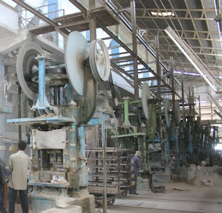
An array of Friction Screw Presses in a Refractory Plant image
Fig.- An Array of Friction Screw Presses in a Refractory Plant

Nevertheless this article is not to discuss the advantages of SOPs or Standardization which will be discussed in a separate post. Here our point of discussion is how to ensure quality in a refractory brick during its green production. For this each and every brick must pass through a process of checking as a part of standard procedure in the process of production. Below is a list of such things (parameters) that have to be checked during green production of refractory bricks as a criterion for their acceptance or before sending them to drier.


GREEN BRICKS CHECKING LIST
1. Size and critical Dimensions as per actual & shrinkage given in the Production Programme (Refer Drawing if required).
2. Quality / Plate mark / Special instructions.
3. Right angle, Centre slope.
4. Warpage, Bulging.
5. Die Plate jam, cleaning.
6. Spongy, Texture.
7. Rags, Corner loose.
8. Lamination, Crack (Hammering).
9. De-airing & Pressing stroke (Set-up approval).
10. Green B.D, Refractory Composition.
11. Sieve analysis report of Powder (Mixture).
12. Free iron in the Powder/Mixrure.

Refractory Lining Installation of Pipes and Chutes in a Furnace

- No comments
7-July-2020
‘Piping’ and ‘Chutes’ are used in furnaces for the purpose of transporting hot air, gases or solid usually accompanied with fine, hot dust particles. Depending on the existing stress, the piping is lined with single layer or multilayer insulating refractory materials. 

Examples for piping with diameters up to 2000 mm are gas piping for Reformers and metal slides in Preheaters of Cement Plants. Examples for piping with diameters above 2000 mm are recirculation shafts in Lignite Power Plants and Hot Blast Mains in Blast Furnace of Steel Plants.

Below given are certain points (rules) must be taken care of while doing refractory lining of pipes, chutes and circular or curved structures in a furnace:

=> Material and personal transport must be coordinated with the piping designer during the planning phase. Manholes, equipment for scaffolds and material transport must be determined.
=> If the refractory lining consists of several layers, each layer should be installed separately or section by section in order to prevent material mix-up.
=> Expansion joints may not be smaller or larger than what is indicated in the drawings. Mortar residue or other contamination (dust etc.) must not get into the expansion joints.
=> Expansion joint bricks, closed bricks and bricks for bevel areas must be measured, finished and installed precisely. Hollow spaces must be avoided due to danger of background currents.
=> If piping is lined on the ground, a trial installation of the closer piece to be fitted into each stand of pipes must be undertaken or it must be lined on site.
=> The lining on the ground is only possible if both piping and refractory designer have already determined length and weight of the pipe chutes. This will help prevent undesired deformations of the lined pipes.
=> In order to prevent transportation damages the lining of pipe chutes having larger diameters should be protected by braces. These braces must be of such a design and make that they can be securely transported and can be easily removed without damaging the lining.
=> The refractory lining dimensions, especially at the ends of pipe chutes, must be precisely observed. Crowding and damage to the refractory lining during assembly should be prevented.                
=> Below expansion joints must be approved and cleared by the piping designer before refractory lining work starts. Special attention must be given to observance of the cold dimensions (initial tension / stress) and flow direction.


Ideal Grain Size Distribution of Refractory Raw Materials Mixture for making Magnesia Carbon Bricks

- 1 comment
6-July-2020
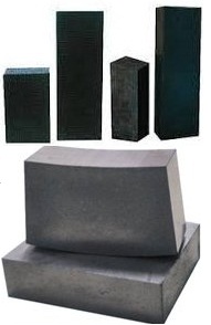
Mag Carbon bricks - representative image
Mag Carbon Bricks
Magnesia carbon refractory bricks (MgO-C) or Carbon containing Magnesite refractories have been extensively used by steel makers for the secondary treatment of steel in basic oxygen furnaces, electric arc furnaces, and ladle furnaces. Mag Carbon refractory bricks are widely used in slag lines of BOF (Basic Oxygen Furnace) because of their superior wear resistance. The service life of Magnesia Carbon refractories used in BOFs have been pushed quite significantly (largely due to slag splashing and gunning improvements) even as the service conditions have become more severe due to the increased operating temperature required for continuous casting and the need to produce cleaner steel.
Mag Carbon bricks are made of high purity magnesia, high quality graphite, antioxidants and some additives with a suitable binder (bonding agent). Selection of raw materials, their grading and grain size distribution (Granulometry) and composition together have ultimate role in the development of various physical properties, microstructure and ultimately thermo-mechanical properties of Mag Carbon refractory bricks (MgO-C). Various different types of MgO (Magnesite) grains provide different levels of corrosion resistance.
From the literature and plant applications it has been established that Magnesia-carbon bricks having 3 mm particle size show better wear resistance as well as a few other characteristics as compared to the bricks with 5 mm size grains.
Graphite, Anti-Oxidants (Additives) and Binders used in the composition of Magnesia Carbon Bricks
The graphite flakes used in these bricks impart -
=> High thermal conductivity
=> Good thermal shock resistance
=> Low thermal expansion
=> Non-wettability by liquid slag
=> Low corrosion rates by slags
Graphite contents of typical bricks range from 4 - 35% natural flake graphite. Since oxygen affinity of carbon is very high so different kinds of antioxidant minerals are used (in fines or superfines) in order to protect refractory material against chemical corrosion. The REDOX reactions in magnesia carbon can be reduced by selection of high purity magnesite, large crystal size and use of graphite with low impurities. Slag corrosion resistance of MgO-C refractories can be improved by use of magnesite grains with less reactivity i.e. fused magnesite grains of high Bulk Density (BD) and high purity.
The above are some of the reasons which explain how selection of various raw materials can affect the performance of magnesia-carbon bricks. More on this aspect and the compositions of Magnesia-carbon refractory bricks will be discussed in a separate post:


Here, our topic is Granulometry i.e. overall grading and the grain size distribution, suitable for the best performance of MgO-C bricks. Grading and the grain size distribution are important as these are directly related with the following properties of Magnesia-carbon bricks:
=> Porosity
=> Mechanical strength
=> Spalling resistance
=> Microstructure and phase development
=> Wear resistance    
From the experience of various trials and performances it has been found that 0 - 4 mm grading is the best for MgO-C refractory bricks for all general applications and also for different shapes like Tap Hole Blocks, Sleeves, etc. (except Slide Gate refractories which will be different).
Bonding agents or binders used in Mag Carbon bricks and other carbon refractory products are immiscible with graphite and other refractory raw materials. At room temperature, they rely on binder to cure. Generally these binders or bonding agents are resin, asphalt or an organic matter and can be divided into three types: phenolic resin, modified asphalt, petroleum cracking by-product category.
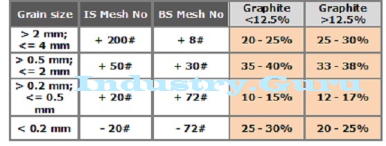
The grain size distribution (granulometry) of the press mixture (powder) for MgO-C bricks with different Graphite percentages as they should be are given in the following table:   

https://www.industry.guru - representative image


Apparent Porosity and True Porosity of Refractory Samples

- No comments

Pores in Refractory Bricks (Porosity)

Porosity is the percentage relationship between the volume of the pore space and the total volume of the refractory sample. Apparent Porosity does not include the volume of the sealed pores. The True Porosity includes the volume of the sealed pores also. The usual difference between the apparent porosity and the true porosity is of the order of 1 to 2 percent unless the proportion of the sealed pores is high. The true porosity figure is the higher than the apparent porosity figure as the true porosity includes the volume of the sealed or closed pores also. The difference between the two values represents the percent volume of closed pores. Porosity can be controlled by the following:


=> By controlling the texture of the brick i.e. by controlling the size distribution of the particles.
=> By the methods of green manufacturing and composition.
=> By controlling the firing temperature, soaking time etc.
=> Quality of raw materials i.e. the inherent grain porosity of the raw materials used.

Higher the porosity, lower will be the strength of the brick. Bricks with lower porosity will have greater resistance to slag attack and more sensitiveness to fluctuations in temperature. Their thermal conductivity will be more.
Suggested Article: Bulk Density of Refractory Samples 

Hence, apparent porosity is the percentage ratio of the void space in the refractory specimen to the total bulk volume of the same. There are two methods used for the determination of apparent porosity of refractory materials which are:

=> Boiling point method, and
=> Evacuation method.

Refractory Samples (Refractory Specimen) measuring 6.5 cm x 6.5 cm x 4 cm is cut from burnt refractory bricks by a cut off wheel from within its core and cleaned any dust or loose particles adhering to its surface and are dried in an oven at 110OC to a constant weight. For graded materials take 3 to 5 mm size grains and dry at 110OC. It can be determined by following the steps given in any of the Standard Methods for Refractory Testing like - ASTM, Indian Standards (IS), Ghost, DIN etc.

True Porosity (%) = {1 - (Apparent Sp. Gr. ÷ True Sp. Gr.)} x 100
Apparent Porosity (%) = {(Soaked Wt - Dry Wt) ÷ (Soaked Wt - Suspended Wt)} x 100

 Related Articles 

Permeability of Refractory Bricks and Monolithics

- No comments

5-July-2020

Permeability of any refractory material is defined as the volume of a gas or air which will pass through a cubic centimeter of the material under a pressure of 1 cm of water per second. 

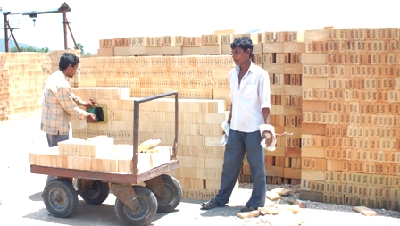
Refractory Bricks being stacked - representative image
Fig - Refractory Bricks being stacked in stock yard

Permeability is calculated by the following formula:
Permeability = (Vol. of gas/air x thickness) ÷ (Area x Time of flow x Pressure difference)

It is determined by forcing a known volume air or gas through a cube. Time of flow, pressure difference and dimensions of specimens are noted. However, there are ready-made apparatuses and systems available in the market for testing permeability of refractory bricks and monolithics. There is no direct dependence permeability has on porosity however, permeability depends upon the existence of closed pores or channel pores and is a measure of these, whereas porosity measures the total pore volume including closed pores.


However, this property permeability for refractory bricks or monolithics become important wherever molten liquid like metal, slag, glass etc. come in contact with the refractory lining i.e. wall of the furnace or container especially, when gas under pressure is present. Due to the anisotropic nature of refractories, the result will depend upon on factors such as the direction of flow and presence or absence of the original skin on the test specimen.

Low permeability is more important than low porosity from the point of view of slag resistance of the refractory. Uniform permeability is an indication of absence of cracks in the refractory.

Related Articles: